
Project Overview
In this project, we will build a 4-digit 7-segment counter using an Arduino Mega (ATmega2560). The system will use three pushbuttons to control the count value (increment, decrement, and reset). We will drive the display using multiplexing and handle button inputs with timer-based scanning—all without using delay().
This blog explains:
- The difference between common anode and common cathode displays.
- How to use hardware timer interrupts for precise timing.
- Step-by-step development from a basic timer template to a full counter application.
Part 1: Understanding 4-Digit 7-Segment Displays
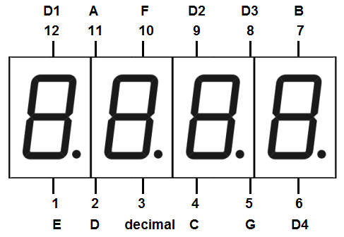
A 7-segment display has 8 LEDs (7 segments + 1 decimal point). In a 4-digit module, each digit shares the same segment lines (a,b,c,d,e,f,g,dp), but each digit has its own common pin.
Common Anode vs Common Cathode
| Feature | Common Anode | Common Cathode |
|---|---|---|
| Common pin | Connected to +5V | Connected to GND |
| To turn ON a segment | Segment pin = LOW (0V) | Segment pin = HIGH (5V) |
| To turn OFF a segment | Segment pin = HIGH | Segment pin = LOW |
| Digit selection | Set common pin HIGH to enable that digit | Set common pin LOW to enable that digit |
In this project: We use a Common Anode display.
- Digit pins (D1-D4) = HIGH = digit ON.
- Segment pins (a,b,c,…) = LOW = segment lit.
Multiplexing Technique
We cannot light all digits at once (too many pins). Instead, we:
- Turn ON only one digit at a time.
- Send the segment pattern for that digit.
- Quickly switch to the next digit.
- Repeat faster than 60Hz → human eye sees all digits lit simultaneously.
Part 2: Hardware Connections
Pin Mapping (Arduino Mega)
cpp// Digit select pins (common anode control)
#define D4 52 // Units digit (rightmost)
#define D3 50 // Tens digit
#define D2 48 // Hundreds digit
#define D1 46 // Thousands digit (leftmost)
// Segment pins (connected to all digits in parallel)
#define dp 22 // Decimal point
#define g 24 // Segment G
#define f 26 // Segment F
#define e 28 // Segment E
#define d 30 // Segment D
#define c 32 // Segment C
#define b 34 // Segment B
#define a 36 // Segment A
// Pushbuttons (using internal pull-up resistors)
#define S1 14 // Increment button
#define S2 15 // Decrement button
#define S3 16 // Reset button
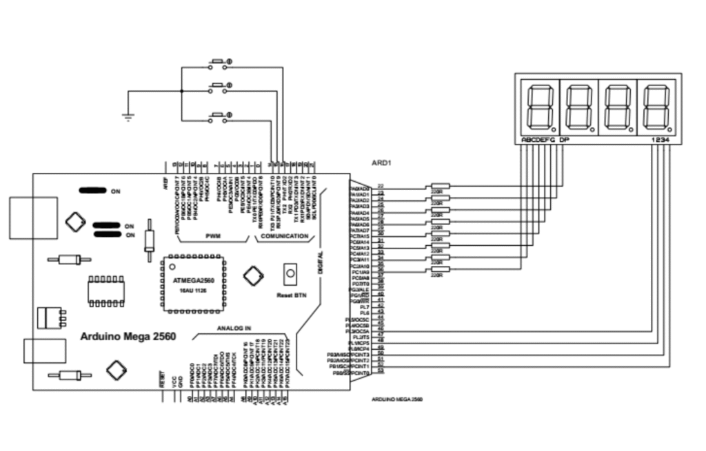
Wiring Summary
| Component | Connection |
|---|---|
| 4-digit common anode display | Segment pins to digital 22-36 (via 220Ω resistors), Digit pins to 46-52 |
| Pushbuttons | One pin to S1/S2/S3, other pin to GND (use INPUT_PULLUP) |
| Power | Arduino 5V and GND |
Part 3: Timer Interrupts – The Heart of Precision
What is a Timer Interrupt?
A timer is a hardware counter inside the ATmega2560 that increments at a fixed rate (16 MHz here). When it reaches a preset value (OCR), it triggers an Interrupt – pausing the main loop, running a special function (ISR), then resuming.
Why use timer interrupts?
- Perfect timing without
delay()blocking. - Multiple tasks can run at different intervals.
- Display multiplexing and button scanning happen in background.
Our Timer Configuration (from base code)
The provided base code configures all 6 timers of the ATmega2560 independently:
cpp#define TIMER0_INTERVAL_US 100 // Used for display scanning
#define TIMER1_INTERVAL_US 100 // Used for button scanning
#define TIMER2_INTERVAL_US 100 // (spare)
#define TIMER3_INTERVAL_US 100000 // (spare)
#define TIMER4_INTERVAL_US 500000 // (spare)
#define TIMER5_INTERVAL_US 1000000 // (spare)
Each timer triggers its own ISR at the specified interval. This allows parallel operation – different tasks run at different rates without interfering.
Part 4: Step-by-Step Code Development
We start from the base timer template and add functions one by one.
Step 1: Basic Timer Setup (Starting Point)
The base program configures all timers in CTC mode. The calc_ocr() function automatically selects the best prescaler and compare value. In setup(), we call configure_all_timers() to start them.
/*
 * ATmega2560 - Parallel 6-Timer CTC Configuration
 * Clock: 16 MHz
 *
 * INTERVAL RANGES:
 * Timers 0,2 (8-bit):   4 µs to 16,384 µs  (0.004 - 16.384 ms)
 * Timers 1,3,4,5 (16-bit): 4 µs to 4,194,304 µs (0.004 - 4194.304 ms)
 *
 * WARNING: Timer0 modifies Arduino millis()/delay()/micros().
 * Set TIMER0_INTERVAL_US to 0 to skip Timer0 and preserve Arduino timing.
 */

#include <avr/io.h>
#include <avr/interrupt.h>

#ifndef F_CPU
  #define F_CPU 16000000UL
#endif

// ============================================================================
// USER CONFIGURATION - Set all 6 intervals independently (microseconds)
// ============================================================================
#define TIMER0_INTERVAL_US    1000     // 8-bit: 4-16384 µs (WARNING: affects millis())
#define TIMER1_INTERVAL_US    10000    // 16-bit: 4-4194304 µs
#define TIMER2_INTERVAL_US    100      // 8-bit: 4-16384 µs
#define TIMER3_INTERVAL_US    100000   // 16-bit: 4-4194304 µs
#define TIMER4_INTERVAL_US    500000   // 16-bit: 4-4194304 µs
#define TIMER5_INTERVAL_US    1000000  // 16-bit: 4-4194304 µs

// ============================================================================
// Timer Configuration Engine
// ============================================================================
typedef struct {
    uint8_t  cs_bits;
    uint16_t prescale;
} Prescaler;

// Standard timers (0,1,3,4,5) prescalers: 1,8,64,256,1024
const Prescaler STD_PRESCALERS[5] = {
    {0b001, 1}, {0b010, 8}, {0b011, 64}, {0b100, 256}, {0b101, 1024}
};

// Timer2 prescalers: 1,8,32,64,128,256,1024 (different bit mapping)
const Prescaler T2_PRESCALERS[7] = {
    {0b001, 1}, {0b010, 8}, {0b011, 32}, {0b100, 64},
    {0b101, 128}, {0b110, 256}, {0b111, 1024}
};

//Functions

/***********/

static inline uint32_t calc_ocr(uint32_t us, uint8_t is16bit, const Prescaler *table, uint8_t entries, uint8_t *cs) {
    uint32_t max_ocr = is16bit ? 65535 : 255;
    uint32_t best_err = 0xFFFFFFFF;
    uint32_t ocr_out = 0;

    for (uint8_t i = 0; i < entries; i++) {
        uint32_t ocr = ((uint64_t)us * F_CPU) / ((uint64_t)table[i].prescale * 1000000UL) - 1;
        if (ocr <= max_ocr) {
            uint32_t actual = ((uint64_t)(ocr + 1) * table[i].prescale * 1000000UL) / F_CPU;
            uint32_t err = (actual > us) ? (actual - us) : (us - actual);
            if (err < best_err) {
                best_err = err;
                ocr_out = ocr;
                *cs = table[i].cs_bits;
            }
        }
    }
    return ocr_out;
}

// Configure single timer
void config_timer(uint8_t n, uint32_t us) {
    if (us == 0) return;  // Skip if interval is 0

    uint8_t cs;
    uint32_t ocr;

    switch(n) {
        case 0: // 8-bit
            ocr = calc_ocr(us, 0, STD_PRESCALERS, 5, &cs);
            TCCR0A = (1 << WGM01);      // CTC mode
            TCCR0B = cs;                 // Prescaler
            OCR0A = (uint8_t)ocr;       // Compare value
            TIMSK0 = (1 << OCIE0A);     // Enable interrupt
            break;

        case 1: // 16-bit
            ocr = calc_ocr(us, 1, STD_PRESCALERS, 5, &cs);
            TCCR1A = 0;
            TCCR1B = (1 << WGM12) | cs;
            OCR1A = (uint16_t)ocr;
            TIMSK1 = (1 << OCIE1A);
            break;

        case 2: // 8-bit with extended prescalers
            ocr = calc_ocr(us, 0, T2_PRESCALERS, 7, &cs);
            TCCR2A = (1 << WGM21);      // CTC mode
            TCCR2B = cs;                 // Prescaler (Timer2 specific)
            OCR2A = (uint8_t)ocr;
            TIMSK2 = (1 << OCIE2A);
            break;

        case 3: // 16-bit
            ocr = calc_ocr(us, 1, STD_PRESCALERS, 5, &cs);
            TCCR3A = 0;
            TCCR3B = (1 << WGM32) | cs;
            OCR3A = (uint16_t)ocr;
            TIMSK3 = (1 << OCIE3A);
            break;

        case 4: // 16-bit
            ocr = calc_ocr(us, 1, STD_PRESCALERS, 5, &cs);
            TCCR4A = 0;
            TCCR4B = (1 << WGM42) | cs;
            OCR4A = (uint16_t)ocr;
            TIMSK4 = (1 << OCIE4A);
            break;

        case 5: // 16-bit
            ocr = calc_ocr(us, 1, STD_PRESCALERS, 5, &cs);
            TCCR5A = 0;
            TCCR5B = (1 << WGM52) | cs;
            OCR5A = (uint16_t)ocr;
            TIMSK5 = (1 << OCIE5A);
            break;
    }
}

// ============================================================================
// Configure ALL timers at once (parallel operation)
// ============================================================================
void configure_all_timers() {
    cli();  // Disable interrupts during configuration

    config_timer(0, TIMER0_INTERVAL_US);
    config_timer(1, TIMER1_INTERVAL_US);
    config_timer(2, TIMER2_INTERVAL_US);
    config_timer(3, TIMER3_INTERVAL_US);
    config_timer(4, TIMER4_INTERVAL_US);
    config_timer(5, TIMER5_INTERVAL_US);

    sei();  // Enable global interrupts - all timers start simultaneously
}

void setup() {
    configure_all_timers();  // One command starts all 6 timers in parallel


}

void loop() {
    // Main application logic
    // All 6 timers run independently in background via ISRs
}

// ============================================================================
// Interrupt Service Routines - Independent Execution
// ============================================================================
ISR(TIMER0_COMPA_vect) {
    // Executes every TIMER0_INTERVAL_US microseconds
    // WARNING: If TIMER0_INTERVAL_US > 0, Arduino millis()/delay() run at different speed


}

ISR(TIMER1_COMPA_vect) {
    // Executes every TIMER1_INTERVAL_US microseconds

}

ISR(TIMER2_COMPA_vect) {
    // Executes every TIMER2_INTERVAL_US microseconds

}

ISR(TIMER3_COMPA_vect) {
    // Executes every TIMER3_INTERVAL_US microseconds

}

ISR(TIMER4_COMPA_vect) {
    // Executes every TIMER4_INTERVAL_US microseconds


}

ISR(TIMER5_COMPA_vect) {
    // Executes every TIMER5_INTERVAL_US microseconds

}
Step 2: Add Pin Definitions and Setup
We add the #define statements and configure pins in setup().
cppvoid setup() {
configure_all_timers();
// Digit pins as outputs
pinMode(D1, OUTPUT); pinMode(D2, OUTPUT);
pinMode(D3, OUTPUT); pinMode(D4, OUTPUT);
// Segment pins as outputs
pinMode(a, OUTPUT); pinMode(b, OUTPUT); pinMode(c, OUTPUT);
pinMode(d, OUTPUT); pinMode(e, OUTPUT); pinMode(f, OUTPUT);
pinMode(g, OUTPUT); pinMode(dp, OUTPUT);
// Button pins with pull-up
pinMode(S1, INPUT_PULLUP);
pinMode(S2, INPUT_PULLUP);
pinMode(S3, INPUT_PULLUP);
// Initial state: all digits OFF, all segments OFF (HIGH for common anode)
digitalWrite(D1, LOW); digitalWrite(D2, LOW);
digitalWrite(D3, LOW); digitalWrite(D4, LOW);
digitalWrite(a, HIGH); digitalWrite(b, HIGH);
digitalWrite(c, HIGH); digitalWrite(d, HIGH);
digitalWrite(e, HIGH); digitalWrite(f, HIGH);
digitalWrite(g, HIGH); digitalWrite(dp, HIGH);
}
Step 3: BCD to 7-Segment Conversion Function
This function takes a digit (0-9) and returns a byte where each bit represents a segment. For common anode, a 0 bit means ON.
cppchar BCD_to_7Segment(int num) {
// Bit format: dp g f e d c b a
// 0 = LED ON (common anode)
switch (num) {
case 0: return 0b11000000; // Segments a,b,c,d,e,f ON
case 1: return 0b11111001; // Segments b,c ON
case 2: return 0b10100100;
case 3: return 0b10110000;
case 4: return 0b10011001;
case 5: return 0b10010010;
case 6: return 0b10000010;
case 7: return 0b11111000;
case 8: return 0b10000000; // All segments ON
case 9: return 0b10010000;
default: return 0b11111111; // All OFF
}
}
Step 4: Display Function
This function writes the segment pattern to the physical pins.
cppvoid DisplayNum(char seg) {
// Write each bit to the corresponding pin
digitalWrite(a, (seg & 0b00000001) ? HIGH : LOW);
digitalWrite(b, (seg & 0b00000010) ? HIGH : LOW);
digitalWrite(c, (seg & 0b00000100) ? HIGH : LOW);
digitalWrite(d, (seg & 0b00001000) ? HIGH : LOW);
digitalWrite(e, (seg & 0b00010000) ? HIGH : LOW);
digitalWrite(f, (seg & 0b00100000) ? HIGH : LOW);
digitalWrite(g, (seg & 0b01000000) ? HIGH : LOW);
digitalWrite(dp, (seg & 0b10000000) ? HIGH : LOW);
}
Step 5: Counter to BCD Conversion
We store the counter value (0-9999) and split it into separate digits.
cppint Counter = 1234; // Starting value
int TH, H, T, U; // Thousands, Hundreds, Tens, Units
void CounterToBCD() {
if (Counter < 0) Counter = 0;
if (Counter > 9999) Counter = Counter % 10000;
TH = (Counter / 1000) % 10;
H = (Counter / 100) % 10;
T = (Counter / 10) % 10;
U = Counter % 10;
}
Step 6: Display Multiplexing Function
This function is called by a timer interrupt. It displays one digit at a time and cycles through all four.
cppvoid ScanDigits() {
CounterToBCD(); // Update digits from Counter
// Turn off all digit commons (prepare for next digit)
digitalWrite(D1, LOW);
digitalWrite(D2, LOW);
digitalWrite(D3, LOW);
digitalWrite(D4, LOW);
static int digit = 0; // Which digit we are showing now
char seg = 0xFF;
switch(digit) {
case 0: seg = BCD_to_7Segment(U); digitalWrite(D4, HIGH); break;
case 1: seg = BCD_to_7Segment(T); digitalWrite(D3, HIGH); break;
case 2: seg = BCD_to_7Segment(H); digitalWrite(D2, HIGH); break;
case 3: seg = BCD_to_7Segment(TH); digitalWrite(D1, HIGH); break;
}
DisplayNum(seg);
digit = (digit + 1) % 4; // Move to next digit
}
Step 7: Button Scanning with Debounce
Buttons are mechanical and bounce. We implement a debounce counter that requires a stable press for ~8ms before registering.
cppvoid ScanButtons() {
const uint8_t DEBOUNCE_TICKS = 80; // 80 * 100µs = 8ms
static uint8_t s1_cnt = 0, s2_cnt = 0, s3_cnt = 0;
// Read buttons (invert because INPUT_PULLUP reads HIGH when not pressed)
bool raw_s1 = !digitalRead(S1);
bool raw_s2 = !digitalRead(S2);
bool raw_s3 = !digitalRead(S3);
// Debounce for S1 (Increment)
if (raw_s1 && s1_cnt < DEBOUNCE_TICKS) s1_cnt++;
else if (!raw_s1 && s1_cnt > 0) s1_cnt–;
if (s1_cnt >= DEBOUNCE_TICKS && !S1_state) {
S1_state = true;
Counter++;
if (Counter >= 10000) Counter = 0;
} else if (s1_cnt < DEBOUNCE_TICKS && S1_state) {
S1_state = false;
}
// S2 (Decrement) – similar logic
// S3 (Reset) – similar logic, sets Counter = 0
}
Step 8: Assign Functions to Timer ISRs
We use Timer0 for display multiplexing (every 100µs) and Timer1 for button scanning (every 100µs).
cppISR(TIMER0_COMPA_vect) {
ScanDigits(); // Refresh display at 100µs per digit = 2.5kHz per digit
}
ISR(TIMER1_COMPA_vect) {
ScanButtons(); // Check buttons every 100µs
}
Part 5: Final Complete Code
Here is the fully integrated program:
cpp#include <Arduino.h>
#include <avr/io.h>
#include <avr/interrupt.h>
// ==================== PIN DEFINITIONS ====================
#define D4 52
#define D3 50
#define D2 48
#define D1 46
#define dp 22
#define g 24
#define f 26
#define e 28
#define d 30
#define c 32
#define b 34
#define a 36
#define S1 14
#define S2 15
#define S3 16
// ==================== GLOBAL VARIABLES ====================
int U = 0, T = 0, H = 0, TH = 0;
int Counter;
bool S1_state = 0, S2_state = 0, S3_state = 0;
// ==================== TIMER CONFIGURATION ====================
#ifndef F_CPU
#define F_CPU 16000000UL
#endif
#define TIMER0_INTERVAL_US 100 // Display scanning
#define TIMER1_INTERVAL_US 100 // Button scanning
#define TIMER2_INTERVAL_US 100 // (spare)
#define TIMER3_INTERVAL_US 100000 // (spare)
#define TIMER4_INTERVAL_US 500000 // (spare)
#define TIMER5_INTERVAL_US 1000000 // (spare)
typedef struct {
uint8_t cs_bits;
uint16_t prescale;
} Prescaler;
const Prescaler STD_PRESCALERS[5] = {
{0b001, 1}, {0b010, 8}, {0b011, 64}, {0b100, 256}, {0b101, 1024}
};
const Prescaler T2_PRESCALERS[7] = {
{0b001, 1}, {0b010, 8}, {0b011, 32}, {0b100, 64},
{0b101, 128}, {0b110, 256}, {0b111, 1024}
};
// Timer calculation and configuration functions (from base template)
static inline uint32_t calc_ocr(uint32_t us, uint8_t is16bit, const Prescaler *table, uint8_t entries, uint8_t *cs) {
uint32_t max_ocr = is16bit ? 65535 : 255;
uint32_t best_err = 0xFFFFFFFF;
uint32_t ocr_out = 0;
for (uint8_t i = 0; i < entries; i++) {
uint32_t ocr = ((uint64_t)us * F_CPU) / ((uint64_t)table[i].prescale * 1000000UL) – 1;
if (ocr <= max_ocr) {
uint32_t actual = ((uint64_t)(ocr + 1) * table[i].prescale * 1000000UL) / F_CPU;
uint32_t err = (actual > us) ? (actual – us) : (us – actual);
if (err < best_err) {
best_err = err;
ocr_out = ocr;
*cs = table[i].cs_bits;
}
}
}
return ocr_out;
}
void config_timer(uint8_t n, uint32_t us) {
if (us == 0) return;
uint8_t cs;
uint32_t ocr;
switch(n) {
case 0: ocr = calc_ocr(us, 0, STD_PRESCALERS, 5, &cs);
TCCR0A = (1 << WGM01); TCCR0B = cs; OCR0A = (uint8_t)ocr; TIMSK0 = (1 << OCIE0A); break;
case 1: ocr = calc_ocr(us, 1, STD_PRESCALERS, 5, &cs);
TCCR1A = 0; TCCR1B = (1 << WGM12) | cs; OCR1A = (uint16_t)ocr; TIMSK1 = (1 << OCIE1A); break;
case 2: ocr = calc_ocr(us, 0, T2_PRESCALERS, 7, &cs);
TCCR2A = (1 << WGM21); TCCR2B = cs; OCR2A = (uint8_t)ocr; TIMSK2 = (1 << OCIE2A); break;
case 3: ocr = calc_ocr(us, 1, STD_PRESCALERS, 5, &cs);
TCCR3A = 0; TCCR3B = (1 << WGM32) | cs; OCR3A = (uint16_t)ocr; TIMSK3 = (1 << OCIE3A); break;
case 4: ocr = calc_ocr(us, 1, STD_PRESCALERS, 5, &cs);
TCCR4A = 0; TCCR4B = (1 << WGM42) | cs; OCR4A = (uint16_t)ocr; TIMSK4 = (1 << OCIE4A); break;
case 5: ocr = calc_ocr(us, 1, STD_PRESCALERS, 5, &cs);
TCCR5A = 0; TCCR5B = (1 << WGM52) | cs; OCR5A = (uint16_t)ocr; TIMSK5 = (1 << OCIE5A); break;
}
}
void configure_all_timers() {
cli();
config_timer(0, TIMER0_INTERVAL_US);
config_timer(1, TIMER1_INTERVAL_US);
config_timer(2, TIMER2_INTERVAL_US);
config_timer(3, TIMER3_INTERVAL_US);
config_timer(4, TIMER4_INTERVAL_US);
config_timer(5, TIMER5_INTERVAL_US);
sei();
}
// ==================== DISPLAY FUNCTIONS ====================
char BCD_to_7Segment(int num) {
switch (num) {
case 0: return 0b11000000; case 1: return 0b11111001;
case 2: return 0b10100100; case 3: return 0b10110000;
case 4: return 0b10011001; case 5: return 0b10010010;
case 6: return 0b10000010; case 7: return 0b11111000;
case 8: return 0b10000000; case 9: return 0b10010000;
default: return 0b11111111;
}
}
void DisplayNum(char seg) {
digitalWrite(a, (seg & 0b00000001) ? HIGH : LOW);
digitalWrite(b, (seg & 0b00000010) ? HIGH : LOW);
digitalWrite(c, (seg & 0b00000100) ? HIGH : LOW);
digitalWrite(d, (seg & 0b00001000) ? HIGH : LOW);
digitalWrite(e, (seg & 0b00010000) ? HIGH : LOW);
digitalWrite(f, (seg & 0b00100000) ? HIGH : LOW);
digitalWrite(g, (seg & 0b01000000) ? HIGH : LOW);
digitalWrite(dp, (seg & 0b10000000) ? HIGH : LOW);
}
void CounterToBCD() {
if (Counter < 0) Counter = 0;
if (Counter > 9999) Counter = Counter % 10000;
TH = (Counter / 1000) % 10;
H = (Counter / 100) % 10;
T = (Counter / 10) % 10;
U = Counter % 10;
}
void ScanDigits() {
CounterToBCD();
digitalWrite(D1, LOW); digitalWrite(D2, LOW);
digitalWrite(D3, LOW); digitalWrite(D4, LOW);
static int digit = 0;
char seg = 0xFF;
switch(digit) {
case 0: seg = BCD_to_7Segment(U); digitalWrite(D4, HIGH); break;
case 1: seg = BCD_to_7Segment(T); digitalWrite(D3, HIGH); break;
case 2: seg = BCD_to_7Segment(H); digitalWrite(D2, HIGH); break;
case 3: seg = BCD_to_7Segment(TH); digitalWrite(D1, HIGH); break;
}
DisplayNum(seg);
digit = (digit + 1) % 4;
}
// ==================== BUTTON FUNCTIONS ====================
void ScanButtons() {
const uint8_t DEBOUNCE_TICKS = 80;
static uint8_t s1_cnt = 0, s2_cnt = 0, s3_cnt = 0;
bool raw_s1 = !digitalRead(S1);
bool raw_s2 = !digitalRead(S2);
bool raw_s3 = !digitalRead(S3);
// S1 Increment
if (raw_s1 && s1_cnt < DEBOUNCE_TICKS) s1_cnt++;
else if (!raw_s1 && s1_cnt > 0) s1_cnt–;
if (s1_cnt >= DEBOUNCE_TICKS && !S1_state) {
S1_state = true; Counter++; if (Counter >= 10000) Counter = 0;
} else if (s1_cnt < DEBOUNCE_TICKS && S1_state) S1_state = false;
// S2 Decrement
if (raw_s2 && s2_cnt < DEBOUNCE_TICKS) s2_cnt++;
else if (!raw_s2 && s2_cnt > 0) s2_cnt–;
if (s2_cnt >= DEBOUNCE_TICKS && !S2_state) {
S2_state = true; Counter–; if (Counter < 0) Counter = 9999;
} else if (s2_cnt < DEBOUNCE_TICKS && S2_state) S2_state = false;
// S3 Reset
if (raw_s3 && s3_cnt < DEBOUNCE_TICKS) s3_cnt++;
else if (!raw_s3 && s3_cnt > 0) s3_cnt–;
if (s3_cnt >= DEBOUNCE_TICKS && !S3_state) {
S3_state = true; Counter = 0;
} else if (s3_cnt < DEBOUNCE_TICKS && S3_state) S3_state = false;
}
// ==================== SETUP & LOOP ====================
void setup() {
configure_all_timers();
pinMode(D1, OUTPUT); pinMode(D2, OUTPUT);
pinMode(D3, OUTPUT); pinMode(D4, OUTPUT);
pinMode(a, OUTPUT); pinMode(b, OUTPUT);
pinMode(c, OUTPUT); pinMode(d, OUTPUT);
pinMode(e, OUTPUT); pinMode(f, OUTPUT);
pinMode(g, OUTPUT); pinMode(dp, OUTPUT);
pinMode(S1, INPUT_PULLUP);
pinMode(S2, INPUT_PULLUP);
pinMode(S3, INPUT_PULLUP);
digitalWrite(D1, LOW); digitalWrite(D2, LOW);
digitalWrite(D3, LOW); digitalWrite(D4, LOW);
digitalWrite(a, HIGH); digitalWrite(b, HIGH);
digitalWrite(c, HIGH); digitalWrite(d, HIGH);
digitalWrite(e, HIGH); digitalWrite(f, HIGH);
digitalWrite(g, HIGH); digitalWrite(dp, HIGH);
}
void loop() {
// All work done in ISRs – main loop is free for other tasks
}
// ==================== INTERRUPT SERVICE ROUTINES ====================
ISR(TIMER0_COMPA_vect) {
ScanDigits();
}
ISR(TIMER1_COMPA_vect) {
ScanButtons();
}
ISR(TIMER2_COMPA_vect) { }
ISR(TIMER3_COMPA_vect) { }
ISR(TIMER4_COMPA_vect) { }
ISR(TIMER5_COMPA_vect) { }
Conclusion
You have built a 4-digit 7-segment counter with three control buttons using timer interrupts. The key takeaways:
- Common anode displays require LOW segment signals to light up.
- Multiplexing allows driving many digits with few pins.
- Timer interrupts provide precise, non-blocking timing for display refresh and button debouncing.
- The base timer template can be reused for any project needing multiple independent timed actions.
Try modifying the code to add features like:
- A decimal point indicator.
- Count-up/down with auto-repeat when holding a button.
- Saving the counter value to EEPROM.